MSD Crank Trigger Setup and Rotor Phasing
Reference: MSD 7530, MSD 7531, MSD 7720, MSD 7730, MSD CRANK TRIGGER INSTRUCTIONS
MSD Crank Trigger on BBC
- Remove mechanical advance mechanism and/or lock it out on the distributor. You should not have any advance mechanism setup in the distributor! There are different ways to disable or lock out advance mechanisms, see your distributor instructions for details.
- Bring the engine up to TDC on #1 Cyl on the compression stroke.
- Roll engine on over to approximately 30 degrees advance BTDC, or whatever base timing you're targeting for full advance on the engine.
- Crank Trigger wheel should be mounted so that one of the four magnets is lined up approximately with the sensor bracket hole when it's in the center position in it's travel. There is only about 20 degrees of adjustment in the Sensor Bracket, so setting the trigger wheel in this fashion should give you plenty of adjustment in both directions. Also make sure the Arrow on the trigger wheel is visible, it should face out (away from the engine). Failure to do so will have the wrong polarity on the magnets and cause false triggering at higher RPMs.
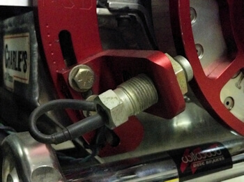
- Install Sensor into adjustable bracket. Sensor should be centered on the trigger wheel front to back. If it isn't, you may have to add or remove shims from the adjustable trigger mount. You should have about .050 to .080 air gap between the sensor and the trigger wheel. Avoid using less gap than .050 as any radial run out in the balancer may cause the wheel to hit the sensor.
Pro Tip: One turn of the 3/4-16 thread sensor is approximately .062" inch. If you screw the sensor all the way in to touch the crank trigger wheel, then turn it out one turn, you should be close to .062 Gap. (From Glenn Payne - MAD Racing Parts) - Set your rotor in the distributor to point to the center of the #1 plug wire terminal. This setting will have your rotor phased at the base timing you have indicated on the balancer.
- Adjust your crank trigger sensor so that it's approximately centered up with the magnet. Note that you'll probably find exact center will be 3-4 degrees retarded when you fire the engine and check the timing with a light. That is normal - you can attempt to take this into account when setting the initial position if you want, but it's often hard to hit it just right. Most people just line them up and the fire the engine to see where the timing actually is at.
- You are now ready to test fire the engine. Have the timing light hooked up and ready to go to check your timing immediately when the engine starts. Note: Too much retard at idle can overheat the exhaust quickly and ruin exhaust header coatings
- Check Rotor Phase while engine is running for best accuracy. Ideally get the rotor tip leading edge right on the front side of the terminal in the cap while watching it with a timing light. To do this, you need a 3/8 or 1/2" hole in your distributor cap right behind the lug on the #1 plug wire position, with the timing light hooked to #1 wire. While the engine is running, point the light down on top of the cap so you can observe the alignment. It helps to paint a white mark on the rotor so it will show up better with the timing light. White typewriter correction fluid works well for marking the rotor.
- Rotor Phasing - Alternative Method - Many racers simply bring the engine up on it's compression stroke and rotate it over to the fully retarded timing value as indicated on the balancer. Then, just adjust the rotor tip till it is pointed directly at the #1 plug wire terminal. While this method may not be quite as accurate as done with the timing light method, it can be very close and can also be used in conjunction with method #9 for verification.
Important Crank Trigger Setup Notes
- If you have a digital ignition, remember most of these have a start retard that often is set to go off at 800 RPM, so if the motor is idling below that RPM, your timing will be affected by whatever setting is in the Digital Box. Make sure your idle RPM is above the start retard setting in order to set your timing correctly. In fact, it would not hurt to have your Laptop plugged into your box to observe that retards are active, or not active at start up.
- Polarity of the green and violet wires on the crank trigger sensor will likely affect your timing. MSD advises that the correct polarity is the one that has the most timing advance on a Digital Ignition. For analog ignitions, this is opposite, and the correct polarity is the one that has the most retard. Do not assume that just because the violet wire is connected to the violet wire that the polarity is correct, you must try both polarities to see which one generates the most advanced setting on a digital ignition (or most retard on analog ignition).
- A non-dial back timing light is recommended. MSD Ignitions can cause erratic readings with dial back lights, so you should avoid using those.
- For Power Adder engine like Nitrous or Boost applications you should phase your distributor at a minimum of 1/2 of total retard. Say you are going to be using 30 degrees of base timing, and pulling 20 degrees out at maximum retard, your fully retarded timing will be 10 degrees. You should phase your distributor at a minimum of 20 degrees, splitting the difference between full advance and full retard. Failure to do this can cause some serious backfiring when your retard is activated.
Also consider in this calculation other additional retards that may also be used when running the car, such as MSD 7761 functions which can often pull your maximum timing retard down very low. For large amounts of timing retard, you may want to phrase your rotor at the maximum retard you will be running when full power is being applied. - You should be using the MSD Shielded Cable from the Crank Trigger Sensor to your ignition box. This will be the two wire cable that attaches to the crank trigger sensor. The shielded model has a third wire that goes to ground on one end. If your cable does not have this ground, it's highly recommended that you get the shielded cable to avoid false signals. It's MSD PN 8862 Shielded Magnetic Pick-up Cable 6 Feet.
- The New MSD Powergrid use a Triangle connector for the crank trigger cable. The new cable is provided with the Grid and has it's own shielded ground wire. This would be equivelant to the PN 8862, but has the correct connector for the Powergrid, and it grounds within the Grid instead of an external ground point.
- The Crank Trigger Sensor wires should be separated from other wire bundles which could cause interference in this wire. If possible, run this cable apart from other wiring.
- Use Blue Loctite on the distributor rotor screws to help prevent them from backing out. A loose distributor rotor can cause severe engine damage by firing cylinders at the wrong time.
- If you are using a crank trigger you will need to check the timing on every cylinder, the timing should be 90 degrees apart from cylinder to cylinder as you go through the firing order. Sometimes the crank trigger wheel will have one magnet in backwards which reverses the polarity, causing 7 degrees more timing on a cylinder! The easiest way is to use a timing light with adjustment knob, set #1 to zero, the next cylinder in order should be 270, then 180, then 90 back to zero as you go threw the firing order.
This tip contributed by Mike Duffy @MDRC - When setting up the Individual Cylinder Timing in MSD Ignitions on a V8, you can easily test the individual cylinder retards by putting 2° retard in cyl #6, then start the engine and check timing on cyl #1 which should show your base timing. Then check the timing on cylinder #6, it should be at -2 degrees that you entered in the MSD for that cyl. #1 and #6 are 360°opposites in firing order so both use TDC as 0!
This tip inspired by Phil Shuler - You can also test your crank trigger magnet polarity using a magnet very easily. Just check to see that an external magnet is pulled to the same side of the magnet on the trigger wheel. Here's a video to show how to do the test real fast.
Flying Magnet Sensor Info
- MSD PN 8276 Non Magnetic Crank Trigger Pickup / Sensor , the 3/4 x16 UNF model should measure 70-90 ohms Resistance. Innovators West also sells a replacement Flying Magnet Crank Trigger Sensor, PN#964 which is a direct replacement. Neil & Parks also has a 3/8" Diameter Made in the USA Crank Trigger sensor with ground that is very popular.
- When a MSD Crank Trigger Sensor is about to die, you will often see huge variations in the RpmDiff trace in the MSD GraphView Software
- The PN 8276 crank trigger sensor Violet wire is positive, and the Green wire is negative.
Crank Trigger Timing Adjustment
You may find it handy to mark the sensor mounting bracket with a sharpie marker somewhere until you memorize which way to move the sensor.
- Right Side (pass) Mounted Sensor - Move Sensor UP to Retard, DOWN to Advance Timing.
- Left Side (driver) Mounted Sensor - Move Sensor DOWN to Retard, UP to Advance Timing.
- Each mark on the MSD Crank Trigger Sensor Mounting Bracket should indicate two degrees of timing.
- Don't try to make timing changes with the engine running.
- Make sure to recheck air gap after moving sensor (.050 - .080 gap).